Quick Start
In this section we will help you install Melody and run you through a simple tutorial that helps you generate your first dataset.
Example: Secondary Voltage Control
This example uses Melody to implement Secondary Voltage Control (SVC) for the IEEE 39-bus New England power system model. The goal of SVC is to maintain voltages at specifically chosen load buses called pilot buses at their nominal values, subjected to random demand fluctuations throughout the day. That can be achieved by adjusting voltage setpoints at the generator buses. In this example, we implement SVC as a standard textbook p-controller that works on the first-order approximation of the power system. Being part of a close-loop control system, SVC is sensitive to the timing of (i) the input signals, which are voltages at pilot buses reported to the SCADA controller by the emulated PMUs, and (ii) the output signals, which are voltage setpoints at generator buses that are sent from the same SCADA controller to the emulated PLCs. It is therefore crucially important that Melody is capable of precisely controlling the advance of virtual simulation time using Kronos.
Setup
The simulation setup is specified in the project configuration file. Below we provide a high level summary:
- System model: IEEE 39-bus New England case
- Power sytem simulation tool: MATPOWER
- Network simulation tool: Mininet
- Application: Secondary Voltage Control
- Generator buses (controlled by SVC): 30, 31, 32, 33, 34, 35, 36, 37, 38, 39
- Pilot buses: 2, 6, 9, 10, 19, 20, 22, 23, 25, 29
- Cyber network: 5-switch clique/ring topology
PMUs
The PMU application is implemented in this Python script. Each PMU is assigned to one pilot bus and is run as a process inside a mininet host. The PMU configuration can be found in the projection configuration file, which is explained here. During runtime, each PMU periodically sends GRPC read requests to the proxy to get the voltage measurement at its pilot bus:
# Creating a list of read requests
# obj_type_to_read = "bus"
# obj_id_to_read = 2 (for pilot bus #2)
# field_type_to_read = "Vm" (Vm for voltage magnitude)
pilot_busses_to_read = [(obj_type_to_read, obj_id_to_read, field_type_to_read)]

# Making a GRPC call to get the voltage measurement
# The call blocks until proxy returns the values
ret = rpc_read(pilot_busses_to_read)
Once receiving the voltage reading, the PMU forwards it to the SCADA controller over UDP:
# pkt is a css_pb2.CyberMessage object that contains information about
# the PMU, including its application ID and voltage measurement
self.host_control_layer.tx_pkt_to_powersim_entity(pkt.SerializeToString())
SCADA controller
The SCADA controller is implemented in this Python script. The SCADA process contains two main threads:
- One that keeps listening to UDP packets sent by PMUs that contain voltage measurements.
- The other that periodically (i) runs the SVC algorithm using the most up-to-date voltage measurements, computes voltage setpoints at the generator buses, and (iii) sends them to the PLCs.
PLCs
The PLC application is implemented in this Python script. Each PLC is assigned to one generator bus that it directly controls. Each PLC runs as a process inside a mininet host. However, unlike PMUs and the SCADA server, PLCs do not run periodically. Instead, each PLC application waits for UDP packets sent by the SCADA controller, parses the packets to extract the voltage setpoints, then updates them to the power system simulation by issueing a GRPC write request to the proxy:
# Making a GRPC call to change the generator voltage setpoint
# The call blocks until proxy returns the write status
rpc_write([(obj_type_to_write, obj_id_to_write, field_type_to_write, voltage_setpoint)])
Note that all packets sent from PMUs to the SCADA controller and from the SCADA controller to the PLCs will travel through the emulated cyber network. Hence, they can be monitored using packet capturing tool. However, the same tool will not capture the GRPC read and write requests – instead, interactions with the Proxy will be logged by the Proxy itself.
Disturbances
Starting the example
Load Kronos once upon restart:
cd ~/Kronos
sudo make load
Switch to the project directory:
cd ~/Melody/srcs/projects/secondary_voltage_control
# set enable_kronos=0 if you wish to run without kronos support
# if enable_kronos is set to 1, ensure that kronos module is pre-loaded
sudo python main.py --enable_kronos=1 --run_time=10
This would run the example for 10 seconds in virtual time.
Generated Log files
Log files and pcaps which are generated are stored inside:
~/Melody/logs/secondary_voltage_control
One log file is generated for each application id.
Results
We setup three following experiments:
- Without Kronos
- With Kronos, minimal network link delay (1ms)
- With Kronos, large network link delay (500ms)
For each experiment, we measure SVC’s step response when there is a step change in reactive power consumption at load bus #4 from 184 to 230 MVAR (25% increment). The data are collected for 25 seconds of virtual time. Using our lab’s setup, it takes about 10 to 15 minutes to complete each experiment.
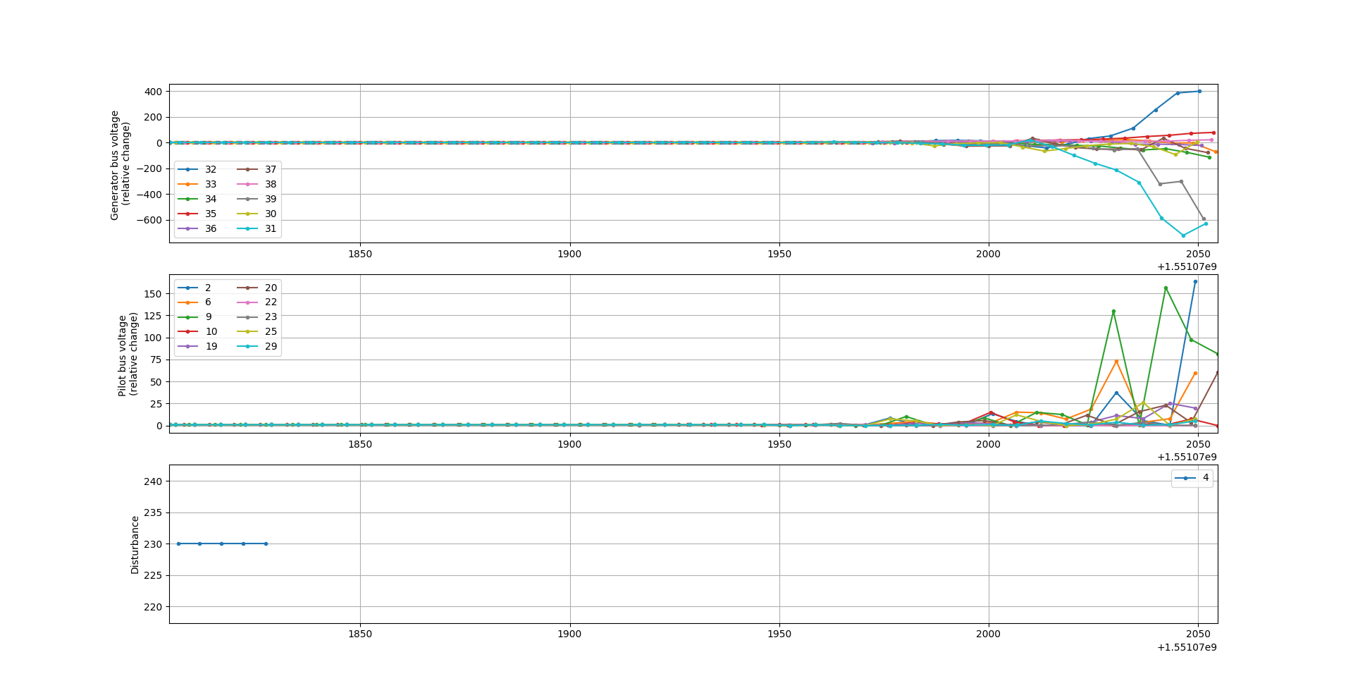
Without Kronos
As can be seen from the graph, without Kronos, the timings of the measurements are totally messed up. Since SVC is time sensitive, that leads to unstable behaviors towards the end of the simulation.
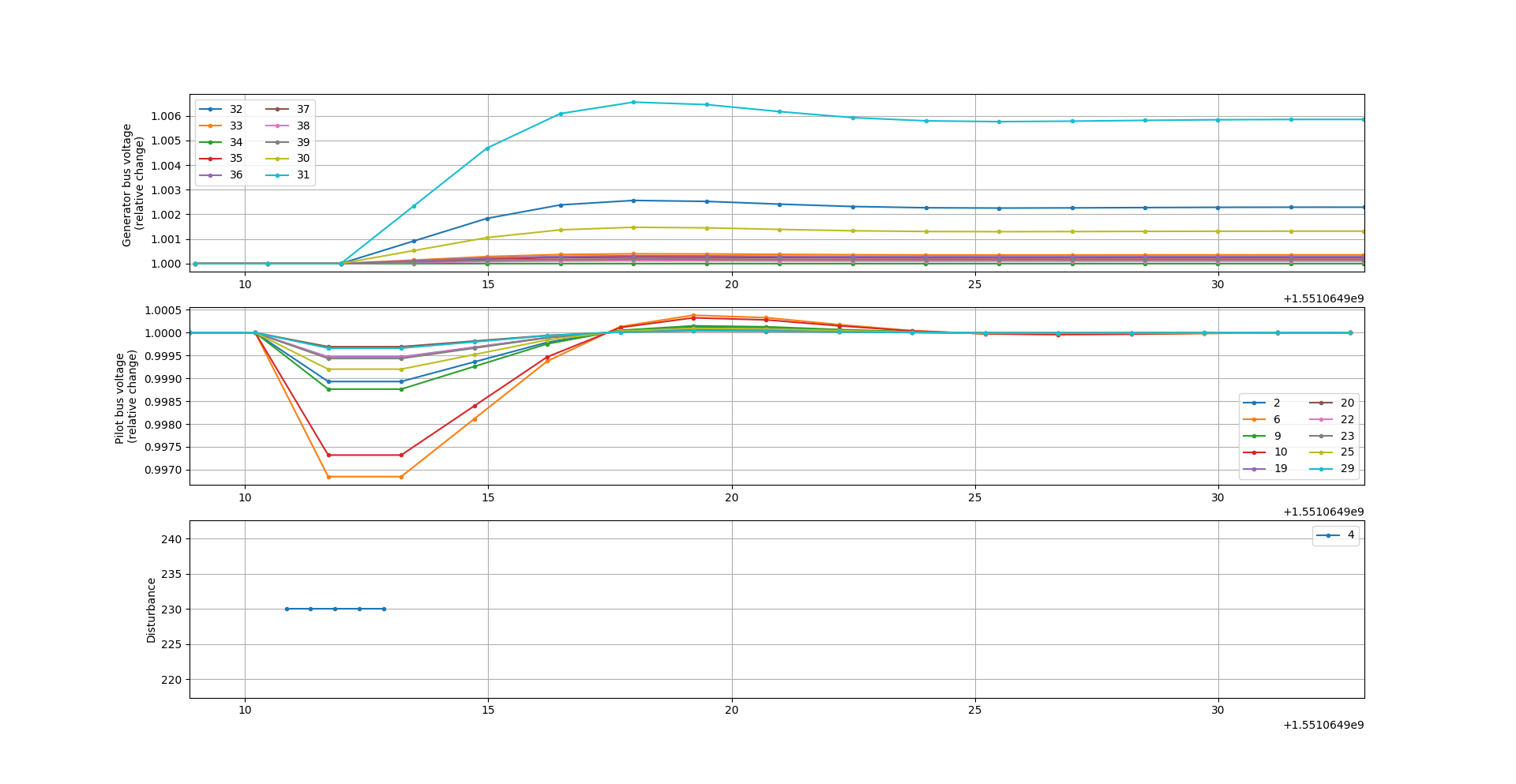
With Kronos and 1ms network link delay
With Kronos, we can see that SVC makes the right adjustments to bring the voltages at pilot buses back to their nominal values, indicated by all relative changes of pilot bus voltages being at 1.0. The voltage setpoints at generator buses slightly overshoot but eventually stabilize within 15 seconds following the onset of the disturbance.
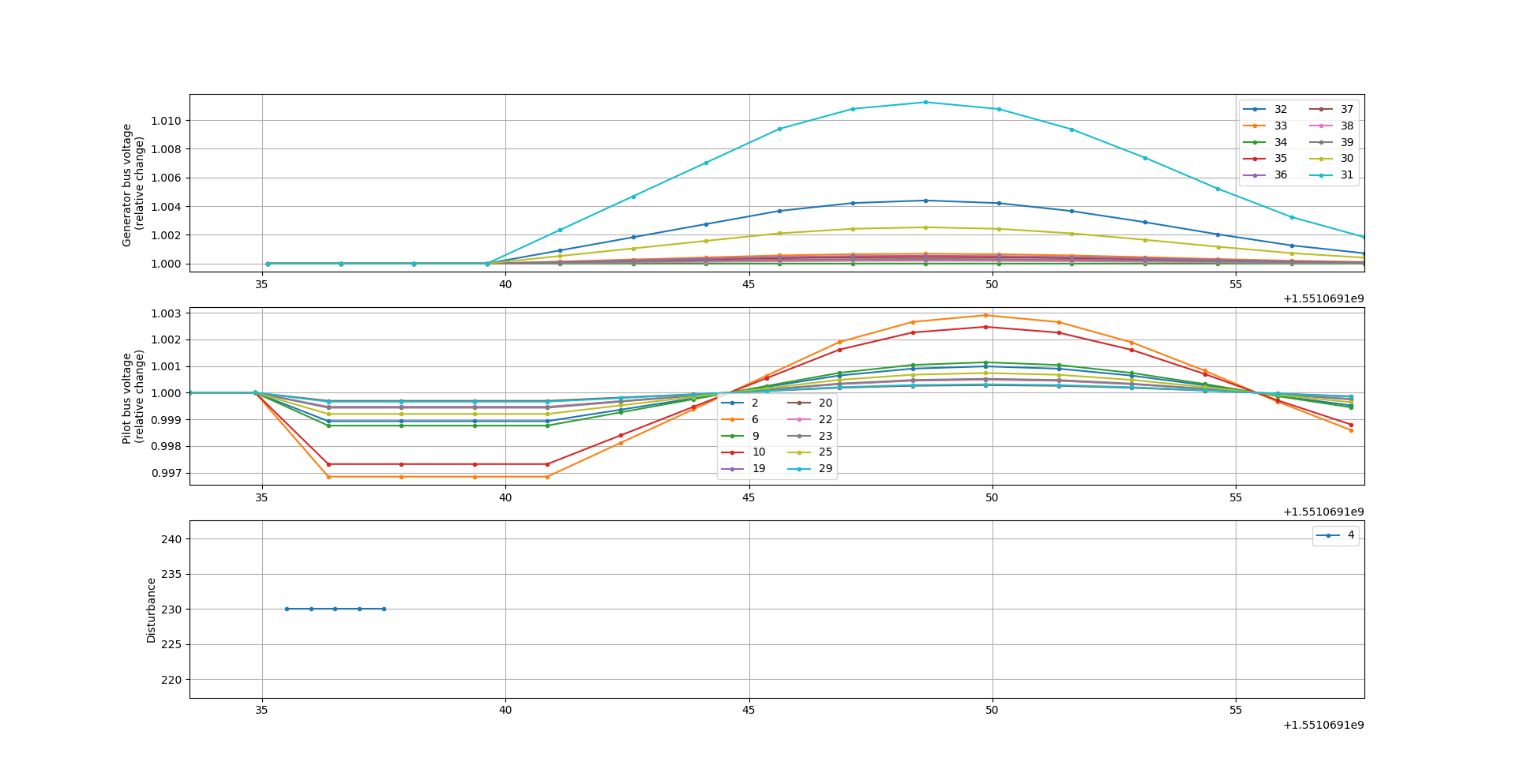
With Kronos and 500ms network link delay
By introducing a delay of 500ms to every network link, it takes on average 2 seconds for each PMU originated packet to reach the SCADA controller (i.e. 4 hops) and another 1.5 seconds for a SCADA controller packet to arrive at the PLCs (3 hops). The net result is a delay of at least 3.5 seconds between the onset of the disturbance and the first time SCADA controller’s response reaches the power system. Such a delay results in the observed oscillation, which can bring the system to instability. This experiment showcases the potential of Melody as a co-simulation tool, i.e. changes in the cyber network setting has the potential of affecting the future states of a cyber-physical system.